I've been having increasing problems with the refuelling/pitstop detection getting stuck on. All the sensors go through a USB gamepad as the switching device, and I'm already on the second of these, so through it was about time for an upgrade.
The race management software I use (Ultimate Racer) is configured for a variety of inputs, including a set of devices made by Phidget. The board I wanted (the Phidget 1012) is around £100 in the UK but I found a little used one on eBay for half that.
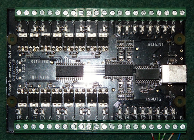
The board is about 3x4 inches with 16 digital inputs, 16 digital outputs and connects to the laptop via USB.
I connected Herman's sensor board to the Phidget as well as the two buttons on the side of the track layout that start/stop and pause/resume the race. (I'm not actually using any of the components on the sensor board on the right of the picture below - it was just convenient to solder the wires that carry the inputs to the Phidget at the top of the board, and means I can revert to using that board if something goes wrong with the Phidget).
So far in testing, the fuel sensor sticking problem has not recurred, so hopefully that's sorted.
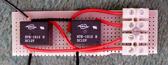
But the added value of the Phidget board are the digital outputs, which allows the powering of other track-related events. The first project for these was controlling the power to each lane of the race layout. This is safer done through relays so I wired together a small circuit board (about 3x1 inches) with compact relays (£2 each from Maplin).
The black wire at top-left is a 12V feed. The two black wires at the bottom go to two different output connectors on the Phidget card. When the output is switched by the race software, the relay switches the current flow through the red wires. These are wired through the block on the right to the power supply to each track. I've wired the relay so by default the red wires are connected (so that the track can be used without having to turn on the laptop or race software).
This affects racing in a couple of ways. The minor benefit is that pressing pause/resume now switches the power off and on to the track. But more importantly, when a racer now runs out of fuel, the software switches the power off to their lane, and they have lost the race.
Here's a diagram that shows the wiring (hybrid of a sketch and a circuit diagram - but hope it's clearer this way). I'm only using power supply but have drawn it twice below to simplify the drawing.
I've got a few other projects in mind for the Phidget outputs - watch this space...
The race management software I use (Ultimate Racer) is configured for a variety of inputs, including a set of devices made by Phidget. The board I wanted (the Phidget 1012) is around £100 in the UK but I found a little used one on eBay for half that.
The board is about 3x4 inches with 16 digital inputs, 16 digital outputs and connects to the laptop via USB.
I connected Herman's sensor board to the Phidget as well as the two buttons on the side of the track layout that start/stop and pause/resume the race. (I'm not actually using any of the components on the sensor board on the right of the picture below - it was just convenient to solder the wires that carry the inputs to the Phidget at the top of the board, and means I can revert to using that board if something goes wrong with the Phidget).
So far in testing, the fuel sensor sticking problem has not recurred, so hopefully that's sorted.
But the added value of the Phidget board are the digital outputs, which allows the powering of other track-related events. The first project for these was controlling the power to each lane of the race layout. This is safer done through relays so I wired together a small circuit board (about 3x1 inches) with compact relays (£2 each from Maplin).
This affects racing in a couple of ways. The minor benefit is that pressing pause/resume now switches the power off and on to the track. But more importantly, when a racer now runs out of fuel, the software switches the power off to their lane, and they have lost the race.
Here's a diagram that shows the wiring (hybrid of a sketch and a circuit diagram - but hope it's clearer this way). I'm only using power supply but have drawn it twice below to simplify the drawing.
I've got a few other projects in mind for the Phidget outputs - watch this space...


No comments:
Post a Comment